Step-by-Step Guide For Linux L3VPN Using GRE/MPLS

Introduction
A Layer 3 Virtual Private Network (L3VPN) allows multiple sites to communicate over a shared IP network as if they were directly connected. In this blog we will go through the configuration of L3VPN on Linux by using:
- Network Namespace (NETNS) to create isolated VPNs on the linux router.
- Multiprotocol Label Switching (MPLS) to label traffic with the respective VPN identifiers.
- Generic Routing Encapsulation (GRE) to create virtual point-to-point tunnels between sites.
By combining MPLS and GRE, you can establish a robust L3VPN. MPLS labels the traffic to ensure it is routed to the correct VPN, while GRE tunnels encapsulate the VPN traffic, allowing it to traverse the underlying IP network securely. This approach leverages the scalability of MPLS and the flexibility of GRE to create an effective L3VPN solution.
Use Case Overview
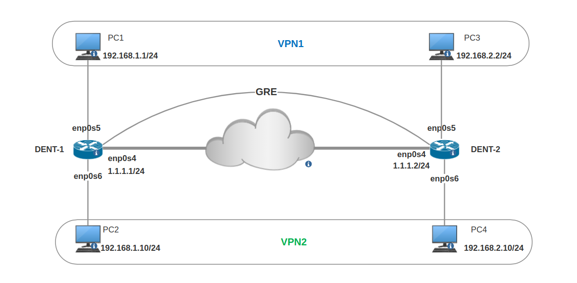
In this use case, we aim to connect two geographically dispersed sites, each with multiple VPNs, over a shared IP network using Linux L3VPN with GRE and MPLS.
Scenario
- Sites: Two sites, edge router
DENT-1andDENT-2, each with two VPNs. - VPNs:
VPN1andVPN2on bothDENT-1andDENT-2. - Network: An IP network connects
DENT-1andDENT-2. - Hosts: Each site has two hosts each host in different VPN,
PC1andPC3inVPN1,PC2andPC4inVPN2. - MPLS Labels: The labeling schema in this example will be 100[X][Y],
where
Xrepresents the site number (1 forDENT-1, 2 forDENT-2), andYrepresents the VPN ID (1vpn1, 2vpn2). e.g. label10021corresponds toDENT-2/vpn1.
Topology
Requirements
Make sure you have the following Linux modules installed:
root@dent-1:~# lsmod
Module                  Size  Used by
ip_gre                 32768  0
gre                    16384  1 ip_gre
mpls_iptunnel          16384  1
mpls_router            40960  1 mpls_iptunnel
mpls_gso               16384  0
vrf                    36864  0
Configuration Steps
DENT-1 configuration:
- Create two
netns,VPN1andVPN2. - To allow routing from
VPN1andVPN2to global netns we need to create two VETHs,veth1with virtual_peerveth1_vpn1forVPN1->globaltraffic flow, andveth2with virtual_peerveth2_vpn2forVPN2->globaltraffic flow. - Add route for prefix
192.168.2.0/24inVPN1to global netns using nexthopveth1_vpn1with via address ofveth1. - Add route for prefix
192.168.2.0/24inVPN2to global netns using nexthopveth2_vpn2with via address ofveth2. - Create two VRFs,
VRF1with table10011, andVRF2with table10012. Each VRF table will have the respective routes for each VPN. - Add ip rule for iif
veth1to table10011, to lookup theVRF1table for any traffic coming fromVPN1to global VRF. - Add ip rule for iif
veth2to table10012, to lookup theVRF2table for any traffic coming fromVPN2to global VRF. - Create GRE interface
GRE1with source1.1.1.1and destination1.1.1.2. - Add the route toward
192.168.2.0/24in both VRFs tables to encapsulate the traffic with the mpls labels and to send the traffic inside the GRE tunnel,VPN1will encapsulate the traffic fromDENt-1toDENT-2with label10021.VPN2will encapsulate the traffic fromDENt-1toDENT-2with label10022.
- For return traffic we will add mpls route in the global netns to pop the label and send the traffic to the right netns according to the incoming label(via veths address).
- Lastly enable mpls for
gre1interface:sysctl -w net.mpls.platform_labels=100000
sysctl -w net.mpls.conf.enp0s4.input=1
DENT-2 Configuration will be the same, but with reversed labeling.
Example Configuration
- ONM-CLI
- IPROUTE2
- NETCONF
# Create network namespaces
netnses-iproute2
  netns vpn1
  netns vpn2
!
# Create VRFs
links-iproute2
  vrf vrf2
    vrf-info table 10012
  vrf vrf1
    vrf-info table 10011
  # Create VETH pairs
  link veth1
    admin-status up
    ip 1.11.11.2/24
    type iproute2-ip-link:veth
    virtual_peer_name veth1_vpn1
  link veth1_vpn1
    admin-status up
    netns vpn1
    ip 1.11.11.1/24
  link veth2
    admin-status up
    ip 2.22.22.2/24
    type iproute2-ip-link:veth
    virtual_peer_name veth2_vpn2
  link veth2_vpn2
    admin-status up
    netns vpn2
    ip 2.22.22.1/24
  # Configure physical interfaces and assign them to namespaces
  link enp0s4
    admin-status up
    ip 1.1.1.1/24
  link enp0s5
    admin-status up
    netns vpn1
    ip 192.168.1.100/24
  link enp0s6
    admin-status up
    netns vpn2
    ip 192.168.1.100/24
  # Create GRE tunnel
  gre gre1
    admin-status up
    tunnel-info local 1.1.1.1
    tunnel-info remote 1.1.1.2
!
# Add routes to leak VPN routes to the global namespace
routes-iproute2
  route 192.168.2.0/24 netns vpn1
    nexthop veth1_vpn1
      via address 1.11.11.2
  route 192.168.2.0/24 netns vpn2
    nexthop veth2_vpn2
      via address 2.22.22.2
  # Add GRE routes in VRF tables for outgoing traffic
  route 192.168.2.0/24 table 10011
    nexthop gre1
      encap mpls-encap label 10021
  route 192.168.2.0/24 table 10012
    nexthop gre1
      encap mpls-encap label 10022
  # Add MPLS routes for incoming traffic to correct VPNs
  mpls-route 10011
    dev veth1
    via 1.11.11.2
  mpls-route 10012
    dev veth2
    via 2.22.22.2
!
# Create IP rules to use VRF tables for traffic
rules-iproute2
  rule 1000
    iif veth1
    action table 10011
  rule 1001
    iif veth2
    action table 10012
# Create network namespaces
ip netns add vpn1
ip netns add vpn2

# Configure physical interfaces and assign them to namespaces
ip link set enp0s4 up
ip address add 1.1.1.1/24 dev enp0s4
ip link set enp0s5 up netns vpn1
ip -n vpn1 address add 192.168.1.100/24 dev enp0s5
ip link set enp0s6 up netns vpn2
ip -n vpn2 address add 192.168.1.100/24 dev enp0s6

# Create VRFs
ip link add vrf1 type vrf table 10011
ip link add vrf2 type vrf table 10012

# Create VETH pairs
ip link add veth1 type veth peer name veth1_vpn1
ip link add veth2 type veth peer name veth2_vpn2
ip link set veth1_vpn1 netns vpn1
ip link set veth2_vpn2 netns vpn2
ip address add 1.11.11.2/24 dev veth1
ip address add 2.22.22.2/24 dev veth2
ip -n vpn1 address add 1.11.11.1/24 dev veth1_vpn1
ip -n vpn2 address add 2.22.22.1/24 dev veth2_vpn2

# Create GRE tunnel
ip link add gre1 type gre local 1.1.1.1 remote 1.1.1.2
ip link set gre1 up

# Add routes to leak VPN routes to the global namespace
ip -n vpn1 route add 192.168.2.0/24 via 1.11.11.2 dev veth1_vpn1
ip -n vpn2 route add 192.168.2.0/24 via 2.22.22.2 dev veth2_vpn2

# Create IP rules to use VRF tables for traffic
ip rule add iif veth1 table 10011
ip rule add iif veth2 table 10012

# Add GRE routes in VRF tables for outgoing traffic
ip route add 192.168.2.0/24 table 10011 dev gre1 encap mpls 10021
ip route add 192.168.2.0/24 table 10012 dev gre1 encap mpls 10022

# Add MPLS routes for incoming traffic to correct VPNs
ip -M route add 10011 via inet 1.11.11.1 dev veth1
ip -M route add 10012 via inet 2.22.22.2 dev veth2
<config>
    <links xmlns="urn:okda:iproute2:ip:link">
        <vrf>
            <name>vrf2</name>
            <vrf-info>
                <table>10012</table>
            </vrf-info>
        </vrf>
        <vrf>
            <name>vrf1</name>
            <vrf-info>
                <table>10011</table>
            </vrf-info>
        </vrf>
        <link>
            <name>veth1</name>
            <admin-status>up</admin-status>
            <ip>
                <address>1.11.11.2/24</address>
            </ip>
            <type>veth</type>
            <virtual_peer_name>veth1_vpn1</virtual_peer_name>
        </link>
        <link>
            <name>veth1_vpn1</name>
            <admin-status>up</admin-status>
            <netns>vpn1</netns>
            <ip>
                <address>1.11.11.1/24</address>
            </ip>
        </link>
        <link>
            <name>veth2</name>
            <admin-status>up</admin-status>
            <ip>
                <address>2.22.22.2/24</address>
            </ip>
            <type>veth</type>
            <virtual_peer_name>veth2_vpn2</virtual_peer_name>
        </link>
        <link>
            <name>veth2_vpn2</name>
            <admin-status>up</admin-status>
            <netns>vpn2</netns>
            <ip>
                <address>2.22.22.1/24</address>
            </ip>
        </link>
        <link>
            <name>enp0s4</name>
            <admin-status>up</admin-status>
            <ip>
                <address>1.1.1.1/24</address>
            </ip>
        </link>
        <link>
            <name>enp0s5</name>
            <admin-status>up</admin-status>
            <netns>vpn1</netns>
            <ip>
                <address>192.168.1.100/24</address>
            </ip>
        </link>
        <link>
            <name>enp0s6</name>
            <admin-status>up</admin-status>
            <netns>vpn2</netns>
            <ip>
                <address>192.168.1.100/24</address>
            </ip>
        </link>
        <gre>
            <name>gre1</name>
            <admin-status>up</admin-status>
            <tunnel-info>
                <local>1.1.1.1</local>
                <remote>1.1.1.2</remote>
            </tunnel-info>
        </gre>
    </links>
    <netnses xmlns="urn:okda:iproute2:ip:netns">
        <netns>
            <name>vpn1</name>
        </netns>
        <netns>
            <name>vpn2</name>
        </netns>
    </netnses>
    <routes xmlns="urn:okda:iproute2:ip:route">
        <route>
            <prefix>192.168.2.0/24</prefix>
            <table>main</table>
            <metric>0</metric>
            <tos>default</tos>
            <netns>vpn1</netns>
            <nexthop>
                <dev>veth1_vpn1</dev>
                <via>
                    <address>1.11.11.2</address>
                </via>
            </nexthop>
        </route>
        <route>
            <prefix>192.168.2.0/24</prefix>
            <table>main</table>
            <metric>0</metric>
            <tos>default</tos>
            <netns>vpn2</netns>
            <nexthop>
                <dev>veth2_vpn2</dev>
                <via>
                    <address>2.22.22.2</address>
                </via>
            </nexthop>
        </route>
        <route>
            <prefix>192.168.2.0/24</prefix>
            <table>10011</table>
            <metric>0</metric>
            <tos>default</tos>
            <netns>1</netns>
            <nexthop>
                <dev>gre1</dev>
                <mpls-encap>
                    <label>10021</label>
                </mpls-encap>
            </nexthop>
        </route>
        <route>
            <prefix>192.168.2.0/24</prefix>
            <table>10012</table>
            <metric>0</metric>
            <tos>default</tos>
            <netns>1</netns>
            <nexthop>
                <dev>gre1</dev>
                <mpls-encap>
                    <label>10022</label>
                </mpls-encap>
            </nexthop>
        </route>
        <mpls-route>
            <label>10011</label>
            <netns>1</netns>
            <dev>veth1</dev>
        </mpls-route>
        <mpls-route>
            <label>10012</label>
            <netns>1</netns>
            <dev>veth2</dev>
        </mpls-route>
    </routes>
    <rules xmlns="urn:okda:iproute2:ip:rule">
        <rule>
            <pref>1000</pref>
            <from>0.0.0.0/0</from>
            <to>0.0.0.0/0</to>
            <tos>default</tos>
            <fwmark>0x00</fwmark>
            <netns>1</netns>
            <iif>veth1</iif>
            <action>
                <table>10011</table>
            </action>
        </rule>
        <rule>
            <pref>1001</pref>
            <from>0.0.0.0/0</from>
            <to>0.0.0.0/0</to>
            <tos>default</tos>
            <fwmark>0x00</fwmark>
            <netns>1</netns>
            <iif>veth2</iif>
            <action>
                <table>10012</table>
            </action>
        </rule>
    </rules>
</config>
Verify
-
Pinging from
PC1toPC2is now working though the mpls/gre tunnel: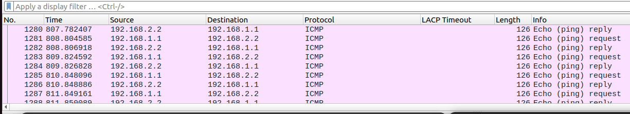
-
Looking at the icmp request send from
PC1we can see it's labeled with10021(DENT-2vpn1label), and encapsulated inside thegre1tunnel: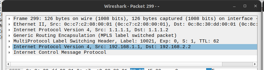
-
Same for incoming icmp response from
PC2we can see DENT-1'svpn1label.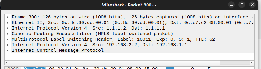
Conclusion
This guide shows how to configure an L3VPN using GRE and MPLS on a Linux router, providing a scalable and flexible solution for routing VPN traffic. However, GRE tunnels lack inherent security. For a more secure approach, consider using IPsec with VTI, which offers encryption and authentication to protect your data.
For more details on Linux network configuration, see our Linux Networking Guide.