Linux VRF Configuration
Linux VRF allows for Layer 3 network segregation by creating multiple routing and forwarding domains. Each domain has its own dedicated routing table, with network links assigned to specific domains.
VRF in Linux does not provide complete network stack isolation, as network namespaces do; it only separates route and FIB lookups.
In this document, we will cover VRF configuration for the following use cases:
- Basic VRF configuration to create multiple routing domain on same router.
- VRF configuration with VLANs.
- VRF configuration with MPLS.
required linux modules
root@dent-1:~# lsmod
Module                  Size  Used by
vrf                    36864  0
mpls_gso               16384  0
mpls_iptunnel          16384  1
mpls_router            40960  1 mpls_iptunnel
Basic VRF configuration
Topology
Configuration
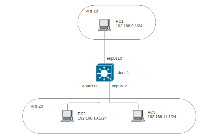
We will create two VRFs vrf10 and vrf20, PC1 and PC2 will be in vrf10 while PC3 in vrf20.
then we should have routing isolation between pcs in vrf10 and vrf20.
- Create
vrf10andvrf20. - Add
enp0s10andenp0s11tovrf10, andenp0s12tovrf20.
When the VRFs are configured, processes can do socket binding to the VRF device using SO_BINDTODEVICE option to source
traffic from that VRF.
- ONM-CLI
- IPROUTE2
- NETCONF
dent-1(config)# links-iproute2
dent-1(config-links-iproute2)# vrf vrf10
dent-1(config-vrf[name='vrf10'])# admin-status up
dent-1(config-vrf[name='vrf10'])# vrf-info table 10
dent-1(config-vrf[name='vrf10'])# exit
dent-1(config-links-iproute2)# vrf vrf20
dent-1(config-vrf[name='vrf20'])# admin-status up
dent-1(config-vrf[name='vrf20'])# vrf-info table 20
dent-1(config-vrf[name='vrf20'])# exit
dent-1(config-links-iproute2)# link enp0s10
dent-1(config-[name='enp0s10'])# admin-status up
dent-1(config-[name='enp0s10'])# master vrf10
dent-1(config-[name='enp0s10'])# ip 192.168.9.11/24
dent-1(config-[name='enp0s10'])# exit
dent-1(config-links-iproute2)# link enp0s11
dent-1(config-[name='enp0s11'])# admin-status up
dent-1(config-[name='enp0s11'])# master vrf20
dent-1(config-[name='enp0s11'])# ip 192.168.10.11/24
dent-1(config-[name='enp0s11'])# exit
dent-1(config-links-iproute2)# link enp0s12
dent-1(config-[name='enp0s12'])# admin-status up
dent-1(config-[name='enp0s12'])# master vrf20
dent-1(config-[name='enp0s12'])# ip 192.168.11.11/24
dent-1(config-[name='enp0s12'])# commit
ip link add name vrf10 mtu 1500 up group 0 type vrf table 10
ip link add name vrf20 mtu 1500 up group 0 type vrf table 20
ip link set name enp0s10 master vrf10
ip address add 192.168.9.11/24 dev enp0s10
ip link set name enp0s11 master vrf20
ip address add 192.168.10.11/24 dev enp0s11
ip link set name enp0s12 master vrf20
ip address add 192.168.11.11/24 dev enp0s12
<config>
    <links xmlns="urn:okda:iproute2:ip:link" xmlns:yang="urn:ietf:params:xml:ns:yang:1">
        <vrf>
            <name>vrf10</name>
            <admin-status>up</admin-status>
            <vrf-info>
                <table>10</table>
            </vrf-info>
        </vrf>
        <vrf>
            <name>vrf20</name>
            <admin-status>up</admin-status>
            <vrf-info>
                <table>20</table>
            </vrf-info>
        </vrf>
        <link>
            <name>enp0s10</name>
            <master>vrf10</master>
            <ip>
                <address>192.168.9.11/24</address>
            </ip>
        </link>
        <link>
            <name>enp0s11</name>
            <master>vrf20</master>
            <ip>
                <address>192.168.10.11/24</address>
            </ip>
        </link>
        <link>
            <name>enp0s12</name>
            <master>vrf20</master>
            <ip>
                <address>192.168.11.11/24</address>
            </ip>
        </link>
    </links>
</config>
Verify
- By examining the routing tables, we can see that each VRF has its own table, and the assigned link is added as a connected route to its respective table.
root@dent-1:~# ip route show table 10
192.168.9.0/24 dev enp0s10 proto kernel scope link src 192.168.9.11
local 192.168.9.11 dev enp0s10 proto kernel scope host src 192.168.9.11


root@dent-1:~# ip route show table 20
192.168.10.0/24 dev enp0s11 proto kernel scope link src 192.168.10.11
local 192.168.10.11 dev enp0s11 proto kernel scope host src 192.168.10.11
192.168.11.0/24 dev enp0s12 proto kernel scope link src 192.168.11.11
local 192.168.11.11 dev enp0s12 proto kernel scope host src 192.168.11.11
- We can see that pings from PC2 to PC3 work (same VRF), while pings from PC2 to PC1 fail (different VRFs).
PC2> ping 192.168.11.1
PING 192.168.11.1 (192.168.11.1) 56(84) bytes of data.
64 bytes from 192.168.11.1: icmp_seq=1 ttl=63 time=0.594 ms
64 bytes from 192.168.11.1: icmp_seq=2 ttl=63 time=1.52 ms
64 bytes from 192.168.11.1: icmp_seq=3 ttl=63 time=1.54 ms
64 bytes from 192.168.11.1: icmp_seq=4 ttl=63 time=1.61 ms
64 bytes from 192.168.11.1: icmp_seq=5 ttl=63 time=0.811 ms
--- 192.168.11.1 ping statistics ---
5 packets transmitted, 5 received, 0% packet loss, time 4016ms
rtt min/avg/max/mdev = 0.594/1.214/1.608/0.424 ms

PC2>  ping 192.168.9.1
PING 192.168.9.1 (192.168.9.1) 56(84) bytes of data.
--- 192.168.9.1 ping statistics ---
5 packets transmitted, 0 received, 100% packet loss, time 4094ms
To allow access between different VRFs, we can use ip rule to match the source and destination,
setting the specific routing table to be used for that traffic.
- ONM-CLI
- IPROUTE2
- NETCONF
dent-1(config)# rules-iproute2
dent-1(config-rules-iproute2)# rule 200 to 192.168.10.1/32
dent-1(config-[pref='200'][to='192.168.10.1/32']# action table 20
dent-1(config-[pref='200'][to='192.168.10.1/32']# exit
dent-1(config-rules-iproute2)# rule 201 to 192.168.9.1/32
dent-1(config-[pref='201'][to='192.168.9.1/32']# action table 10
dent-1(config-[pref='201'][to='192.168.9.1/32']# commit
ip rule add pref 200 to 192.168.10.1/32 table 20
ip rule add pref 201 to 192.168.9.1/32 table 10
<config>
    <rules xmlns="urn:okda:iproute2:ip:rule" xmlns:yang="urn:ietf:params:xml:ns:yang:1">
        <rule>
            <pref>200</pref>
            <from>0.0.0.0/0</from>
            <to>192.168.10.1/32</to>
            <tos>default</tos>
            <fwmark>0x00</fwmark>
            <action>
                <table>20</table>
            </action>
        </rule>
        <rule>
            <pref>201</pref>
            <from>0.0.0.0/0</from>
            <to>192.168.9.1/32</to>
            <tos>default</tos>
            <fwmark>0x00</fwmark>
            <action>
                <table>10</table>
            </action>
        </rule>
    </rules>
</config>
Now PC1 and PC2 should be able to ping each other.
PC2> ping 192.168.9.1
PING 192.168.9.1 (192.168.9.1) 56(84) bytes of data.
64 bytes from 192.168.9.1: icmp_seq=1 ttl=63 time=1.15 ms
64 bytes from 192.168.9.1: icmp_seq=2 ttl=63 time=1.69 ms
64 bytes from 192.168.9.1: icmp_seq=3 ttl=63 time=1.90 ms
VRF with VLANs
Just as we can achieve routing isolation by assigning Layer 3 links to specific VRFs,
we can also assign VLANs to specific VRFs.
For instance,VLAN10 and VLAN20 can be added to VRFx while VLAN30 and VLAN40 can be added to VRFy.
Topology
Configuration
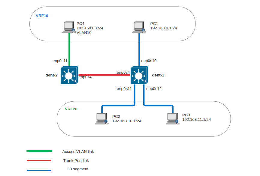
The requirement here is to have PC4 be part of VRF10,
allowing it to ping PC1 (VRF10) but not PC2 and PC3 (VRF20).
To achieve this, apply the following configurations:
On dent-2:
- Create bridge
br1withvlan_filteringenabled. - Add
enp0s11tobr1and addVLAN10to it withPVIDanduntaggedset (access port). - Add
enp0s4tobr1and addVLAN10to it withoutPVIDanduntaggedset (trunk port).
On dent-1:
- Create bridge
br1withvlan_filteringenabled. - Add
enp0s4tobr1and configureVLAN10withoutPVIDanduntaggedset (trunk port). - Create vlan interface
br1.10and add it toVRF10. - Add
VLANid 10 tobr1withselfoption set. - On
PC4, setbr1.10ip as default gateway.
For more details about VLAN configuration please check VLANs Guide.
- ONM-CLI
- IPROUTE2
- NETCONF
dent-1# conf t
dent-1(config)# links-iproute2
dent-1(config-links-iproute2)# bridge br1
dent-1(config-bridge[name='br1'])# admin-status up
dent-1(config-bridge[name='br1'])# br-info stp_state 1
dent-1(config-bridge[name='br1'])# br-info vlan_filtering 1
dent-1(config-bridge[name='br1'])# bridge-conf vlan 10
dent-1(config-vlan[vid='10'])# self true
dent-1(config-vlan[vid='10'])# exit
dent-1(config-bridge[name='br1'])# exit
dent-1(config-links-iproute2)# link enp0s4
dent-1(config-[name='enp0s4'])# admin-status up
dent-1(config-[name='enp0s4'])# master br1
dent-1(config-[name='enp0s4'])# bridge-conf vlan 10
dent-1(config-vlan[vid='10'])# exit
dent-1(config-links-iproute2)# vlan br1.10
dent-1(config-[name='br1.10'])# device br1
dent-1(config-[name='br1.10'])# master vrf10
dent-1(config-[name='br1.10'])# vlan-info id 10
dent-1(config-[name='br1.10'])# admin-status up
dent-1(config-[name='br1.10'])# ip 192.168.8.11/24
dent-1(config-[name='br1.10'])# commit
ip link add name br1 mtu 1500 up type bridge stp_state 1 vlan_filtering 1
bridge vlan add vid 10 dev br1 self
ip link set name enp0s4 up master br1
ip link add name br1.10 link br1 master vrf10 up type vlan id 10
ip address add 192.168.8.11/24 dev br1.10
<config>
    <links xmlns="urn:okda:iproute2:ip:link" xmlns:yang="urn:ietf:params:xml:ns:yang:1">
        <link>
            <name>enp0s4</name>
            <admin-status>up</admin-status>
            <master>br1</master>
            <bridge-conf>
                <vlan>
                    <vid>10</vid>
                </vlan>
            </bridge-conf>
        </link>
        <bridge>
            <name>br1</name>
            <admin-status>up</admin-status>
            <br-info>
                <stp_state>1</stp_state>
                <vlan_filtering>1</vlan_filtering>
            </br-info>
            <bridge-conf>
                <vlan>
                    <vid>10</vid>
                    <self>true</self>
                </vlan>
            </bridge-conf>
        </bridge>
        <vlan>
            <name>br1.10</name>
            <admin-status>up</admin-status>
            <master>vrf10</master>
            <device>br1</device>
            <ip>
                <address>192.168.8.11/24</address>
            </ip>
            <vlan-info>
                <id>10</id>
            </vlan-info>
        </vlan>
    </links>
</config>
Verify
Now PC4 can ping PC1 but not PC2 or PC3.
PC4> ping 192.168.9.1
PING 192.168.9.1 (192.168.9.1) 56(84) bytes of data.
64 bytes from 192.168.9.1: icmp_seq=1 ttl=63 time=1.51 ms
64 bytes from 192.168.9.1: icmp_seq=2 ttl=63 time=1.53 ms
64 bytes from 192.168.9.1: icmp_seq=3 ttl=63 time=1.93 ms
64 bytes from 192.168.9.1: icmp_seq=4 ttl=63 time=3.62 ms


PC4> ping 192.168.10.1
PING 192.168.10.1 (192.168.10.1) 56(84) bytes of data.
--- 192.168.10.1 ping statistics ---
4 packets transmitted, 0 received, 100% packet loss, time 1021ms
VRF with MPLS
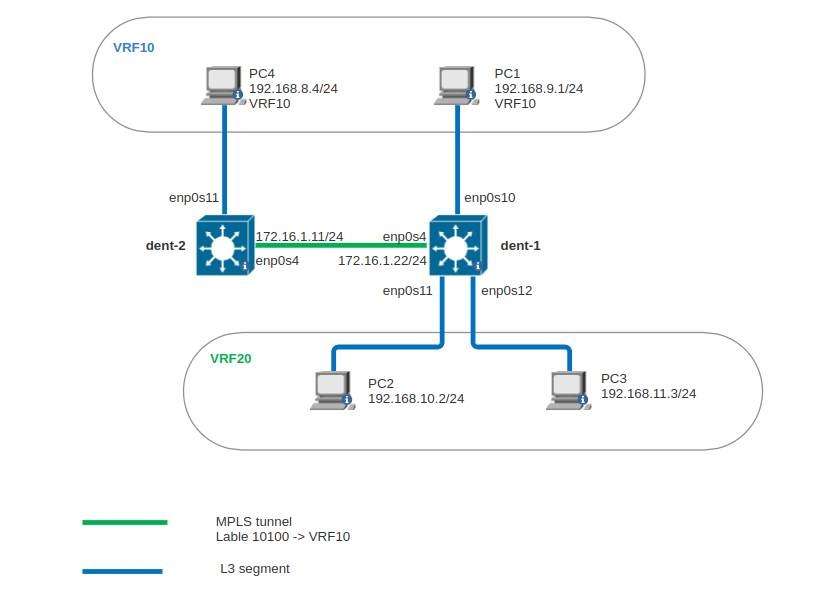
We can utilize VRF and MPLS to establish a static L3VPN network.
In this example, we will configure dent-1 and dent-2 to create an L3VPN (VRF10)
and use MPLS to tunnel traffic between dent-1's VRF10 and dent-2's VRF10 network.
We'll focus on the configuration for dent-1; the configuration for dent-2 will
be identical except for the numbering.
Topology
Configuration
Before starting, ensure the following:
- The required Linux modules are installed:
root@dent-1:~# lsmod
Module                  Size  Used by
vrf                    36864  0
mpls_gso               16384  0
mpls_iptunnel          16384  1
mpls_router            40960  1 mpls_iptunnel
- MPLS is enabled:
root@dent-1:~# sysctl -w net.mpls.platform_labels=100000
root@dent-1:~# sysctl -w net.mpls.conf.enp0s4.input=1
- ONM-CLI
- IPROUTE2
- NETCONF
dent-1(config)# links-iproute2
dent-1(config-links-iproute2)# vrf vrf10
dent-1(config-vrf[name='vrf10'])# admin-status up
dent-1(config-vrf[name='vrf10'])# vrf-info table 10
dent-1(config-vrf[name='vrf10'])# exit
dent-1(config-links-iproute2)# link enp0s10
dent-1(config-[name='enp0s10'])# master vrf10
dent-1(config-[name='enp0s10'])# admin-status up
dent-1(config-[name='enp0s10'])# ip 192.168.9.11/24
dent-1(config-[name='enp0s10'])# exit
dent-1(config-links-iproute2)# link enp0s4
dent-1(config-[name='enp0s4'])# admin-status up
dent-1(config-[name='enp0s4'])# ip 172.16.1.11/24
dent-1(config-[name='enp0s4'])# exit
dent-1(config-links-iproute2)# exit
dent-1(config)# routes-iproute2
dent-1(config-routes-iproute2)# route 192.168.8.0/24 table 10
dent-1(config-[prefix='192.168.8.0/24'][table='10'][metric='0'][tos='# nexthop enp0s4
dent-1(config-nexthop[dev='enp0s4'])# encap mpls-encap label 10100
dent-1(config-nexthop[dev='enp0s4'])# via address 172.16.1.11
dent-1(config-nexthop[dev='enp0s4'])# exit
dent-1(config-[prefix='192.168.8.0/24'][table='10'][metric='0'][tos='# exit
dent-1(config-routes-iproute2)# mpls-route 10100
dent-1(config-[label='10100'])# dev vrf10
dent-1(config-[label='10100'])# commit
ip link add name vrf10 mtu 1500 up group 0 type vrf table 10
ip link set name enp0s4 up
ip address add 172.16.1.11/24 dev enp0s4
ip link set name enp0s10 up master vrf10
ip address add 182.168.8.11/24 dev enp0s10
ip route add 192.168.8.0/24 table 10 nexthop dev enp0s4 encap mpls 10100 via 172.16.1.11
ip -M route add 10100 dev vrf10
<config>
    <links xmlns="urn:okda:iproute2:ip:link" xmlns:yang="urn:ietf:params:xml:ns:yang:1">
        <vrf>
            <name>vrf10</name>
            <admin-status>up</admin-status>
            <vrf-info>
                <table>10</table>
            </vrf-info>
        </vrf>
        <link>
            <name>enp0s4</name>
            <admin-status>up</admin-status>
            <ip>
                <address>172.16.1.11/24</address>
            </ip>
        </link>
        <link>
            <name>enp0s10</name>
            <admin-status>up</admin-status>
            <master>vrf10</master>
            <ip>
                <address>182.168.8.11/24</address>
            </ip>
        </link>
    </links>
    <routes xmlns="urn:okda:iproute2:ip:route" xmlns:yang="urn:ietf:params:xml:ns:yang:1">
        <route>
            <prefix>192.168.8.0/24</prefix>
            <table>10</table>
            <metric>0</metric>
            <tos>default</tos>
            <nexthop>
                <dev>enp0s4</dev>
                <mpls-encap>
                    <label>10100</label>
                </mpls-encap>
                <via>
                    <address>172.16.1.11</address>
                </via>
            </nexthop>
        </route>
        <mpls-route>
            <label>10100</label>
            <dev>vrf10</dev>
        </mpls-route>
    </routes>
</config>
As you can see, we are encapsulating the outgoing traffic with MPLS label 10100 (PUSH)
using the command encap mpls-encap label 10100. For incoming traffic with MPLS label 10100,
we use mpls-route to direct it into VRF10 (POP) with the following commands:
dent-1(config-routes-iproute2)# mpls-route 10100
dent-1(config-[label='10100'])# dev vrf10
dent-1(config-[label='10100'])# commit
Verify
- Now
PC1can pingPC4
PC1> ping 192.168.8.4
PING 192.168.8.4 (192.168.8.4) 56(84) bytes of data.
64 bytes from 192.168.8.4: icmp_seq=1 ttl=62 time=1.40 ms
64 bytes from 192.168.8.4: icmp_seq=2 ttl=62 time=1.53 ms
64 bytes from 192.168.8.4: icmp_seq=3 ttl=62 time=1.51 ms
64 bytes from 192.168.8.4: icmp_seq=4 ttl=62 time=1.61 ms
64 bytes from 192.168.8.4: icmp_seq=5 ttl=62 time=1.51 ms
64 bytes from 192.168.8.4: icmp_seq=6 ttl=62 time=1.99 ms
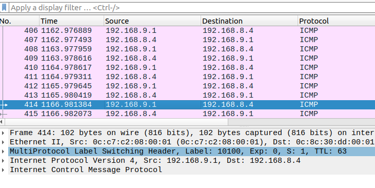
- In the following captures, we can observe that the traffic has the MPLS label
10100: